multimeter
Setting up and testing for voltage
Setting up your multi- meter
Now the first thing u got to do is connect the probes to the multi-meter....the black probe should go to the common terminal and therefore the red probe should go to the connection marked V or VRMA.
Now that you have finished setting up the multi-meter, you can start testing for voltage.
Testing for voltage is as easy as it gets but for a beginner. so in this ill try and make it as simple as it gets
Step 1
After the multi-meter is all set up you can go ahead and observe the voltage that should be coming in on the device that u are testing. On the multi-meter the voltage will be marked V.
Therefore if the device says the voltage that should be coming in is 108V then set the multi-meter one click above that voltage.
 |
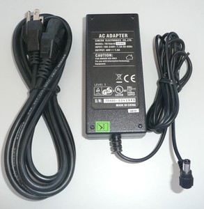
| So on this device a charger the voltage is measured as 108V |
Step 2
After doing all of that....you can start testing the voltage by putting the leads( the metal part of the cables) to the testing location. so now the multi-meter should be reading 108V.
Testing for Resistance
So testing for resistance is completely different from testing for voltage, In testing for resistance there a chance that you could damage the multi-meter or maybe hurt your self. Now testing for resistance, The device, chord or anything thing your testing should be unplugged and de-energized....meaning anything that u are testing should not have any form of power in it.
Wires
Step 1
As said in the text above the device should be unplugged and de-energized. For this example we would be testing the resistance in a charger, so the first thing you should do is unplug the charger and decide which part of the charger you will be testing first.
Step 2
Set the dial on the multi-meter to the highest form of resistance. Then to test if the wire is good and working you'll put the leads at either end of the charger. if the reading comes back zero then the part of the charger that u tested has no resistance so its good. Now do the same to the other part of the wire and if the test comes back other than zero that means that the part of the wire that you tested has a breakage or some form of the wire.
Fuses
Testing fuses is basically the same as testing for continuity but in testing fuses.
Step 1
Remove a legs off the fuse or remove the fuse whole and you would therefore put negative on one end and positive on the other end and the same concept applies as to when your testing wires. remember to turn the dial on the to the highest form of resistance.
Switches
now testing switches is just like fuses.
Step 1
Remove the switch because no power should be running through the component, with the multi-meter on the highest form of resistance you wound place the leads in the proper testing location.
I'll be updating this topic as the time goes so stay turned!!😉

Comments
Post a Comment